domingo, 31 de janeiro de 2016

Módulo RF 434MHz - Arquivo 011

Referência:
http://labdegaragem.com/profiles/blogs/como-utilizar-os-modulos-rf-link-315mhz-434mhz
https://www.pjrc.com/teensy/td_libs_VirtualWire.html

Lista de Materiais:
IDE Arduino 1.0.6
1x  Board Arduino UNO
1x  Board Arduino NANO
2x  Protoboard 830 furos
1x  Cabo USB-A male to USB-B male 
1x  Cabo USB-A male to USB-Mini male
1x  Conj. de fios jumper p/ protoboard
1x  Módulo receptor 434MHz
1x  Módulo transmissor 434MHz
2x  Antena telescópica
4x  Push Button
4x  Led vermelho
4x  Resistor 220R 1/4w
4x  Resistor 10k 1/4w

Montagem:


Firmware:
RF Transmitter
#include <VirtualWire.h> 

char *nibble = "0000"; 

int le_pino; 

void setup(){
  vw_set_ptt_inverted(true);
  vw_setup(2000);
  vw_set_tx_pin(2);

  for(int i=3; i<=6; i++){
    pinMode(i, INPUT_PULLUP);
  }
}
void loop(){
  int j=0;
  for(int i=3;i<=6;i++,j++){
    le_pino = digitalRead(i);
    if(le_pino == 1){
      while(le_pino == 1) le_pino = digitalRead(i); 
      nibble[j] = '1'; 
    }
    else nibble[j] = '0'; 
  }
vw_send((uint8_t *)nibble, strlen(nibble)); 
  vw_wait_tx(); 

}

RF Receiver
#include <VirtualWire.h>

void setup(){
  vw_set_ptt_inverted(true);
  vw_setup(2000);
  vw_set_rx_pin(2);
  vw_rx_start();

  for(int i=3;i<=6;i++){
    pinMode(i, OUTPUT);
  }
}

void loop(){
  uint8_t buf[VW_MAX_MESSAGE_LEN]; 
  uint8_t buflen = VW_MAX_MESSAGE_LEN; 

  if(vw_get_message(buf, &buflen)){
    int j=3;
    for (int i = 0; i < buflen; i++,j++){
      buf[i] = buf[i] - 48; 
      if(buf[i] == 1){
        digitalWrite(j,!digitalRead(j));
      }
    }
  }
}

Download: VirtualWire.h

quinta-feira, 28 de janeiro de 2016

Dimmer de 2 canais - Arquivo 010

Referência:
http://www.instructables.com/id/3-channel-Dimmerfader-for-Arduino-or-other-microco/step2/3-channel-Dimmerfader-for-Arduino-or-other-microco/
http://br-arduino.org/2016/04/arduino-interrupcoes-timer1.html

Lista de Materiais:
IDE Arduino 1.0.6
1x  Board Arduino MEGA 2560
1x  Cabo USB-A male to USB-B male 
2x  Lâmpada incandescente 40w 127Vac
2x  Bocal para lâmpada
1x  Shield Mega Relay & Dimmer V.2.1 

Montagem:


Firmware 01:
int AC_LOAD = 5;             // Output to Opto Triac pin
int dimming;                      // Dimming level (0-128)  0 = ON, 128 = OFF
//*******************************************************************************
void setup(){
  pinMode(AC_LOAD, OUTPUT);
  attachInterrupt(0, zero_crosss_int, RISING);
}
//*******************************************************************************
void zero_crosss_int() {
  int dimtime = (65*dimming);      
  delayMicroseconds(dimtime);                      // Off cycle
  digitalWrite(AC_LOAD, HIGH);                 // triac firing
  delayMicroseconds(8.33);                            // triac On propogation delay
  digitalWrite(AC_LOAD, LOW);                 // triac Off
}
//*******************************************************************************
void loop(){
  dimming = 100;  
}

Firmware 02:
#include <TimerOne.h>  
         
#define PINS 2
//*******************************************************************************
volatile int pinCount[PINS];    
volatile boolean zero_cross=0;  
int AC_pins[] = {4,5};        
int AC_dim[PINS];           
int freqStep = 65;   
//*******************************************************************************
void setup() {
  for(int a=0; a < PINS; a++) { 
   pinMode(AC_pins[a],OUTPUT);
   pinCount[a] = 0;            
   AC_dim[a] = 0;              
  }
  attachInterrupt(0, zero_cross_detect, FALLING); 
  Serial.begin(9600);
  Timer1.initialize(freqStep);                   
  Timer1.attachInterrupt(dim_check, freqStep);                                               
}
//*******************************************************************************
void zero_cross_detect() {                                 
   zero_cross = 1;             
}                                
//*******************************************************************************
void dim_check() {                
 if(zero_cross == 1) {            
   for(int a=0; a < PINS; a++) {
     if(pinCount[a] >= AC_dim[a]) {    
       digitalWrite(AC_pins[a], HIGH);   
       delayMicroseconds(5);              
       digitalWrite(AC_pins[a], LOW);    
       pinCount[a] = 0;            
       zero_cross = 0;                        
     } else {
       pinCount[a]++;                    
     }    
   }
 }
}
//*******************************************************************************
void loop() {
 for(int i=0; i<127; i ++) {
   for(int a=0; a < PINS; a++) {
      int ii = i+42;          
      if(ii > 127) ii -= 127;
      AC_dim[a] = ii;
    }
    delay(50);
  }
}

Download: TimerOne.h

segunda-feira, 25 de janeiro de 2016

Servo Motor Hobbico Cs60- Arquivo 009

Referência:
Exemplo da biblioteca Servo.h

Lista de Materiais:
IDE Arduino 1.0.6
1x  Board Arduino UNO
1x  Protoboard 830 furos
1x  Cabo USB-A male to USB-B male 
1x  Conj. de fios jumper p/ protoboard
1x  Servo motor Hobbico Cs60

Montagem:


Firmware 01:
#include <Servo.h> 

Servo myservo;                                       
int pos = 0;               

void setup() { 
  myservo.attach(9);   


void loop() { 
  for(pos = 0; pos < 180; pos += 1){      
    myservo.write(pos);                           
    delay(15);                                            
  } 
  for(pos = 180; pos>=1; pos-=1){                                    
    myservo.write(pos);                            
    delay(15);                                          
  } 


Firmware 02:
#include <Servo.h> 

Servo myservo;                      
int potpin = 0;                      
int val;                                 

void setup() { 
  myservo.attach(9);                


void loop() { 
  val = analogRead(potpin);          
  val = map(val, 0, 1023, 0, 179);       
  myservo.write(val);                                
  delay(15);                                                  
}

Download: Servo.h

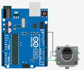
Encoder EC16-2 - Arquivo 008

Referência:
http://bildr.org/2012/08/rotary-encoder-arduino/
http://www.multiwingspan.co.uk/arduino.php?page=rotary2

Lista de Materiais:
IDE Arduino 1.0.6
1x  Board Arduino UNO
1x  Protoboard 830 furos
1x  Cabo USB-A male to USB-B male 
1x  Conj. de fios jumper p/ protoboard
1x  Encoder EC16-2 NHBY

Montagem:


Firmware 01 - Com utilização de Interrupção:
int encoderPin1 = 2;
int encoderPin2 = 3;

volatile int lastEncoded = 0;

volatile long encoderValue = 0;

long lastencoderValue = 0;


int lastMSB = 0;

int lastLSB = 0;
//**************************************************************************** 
void setup() {
  Serial.begin (9600);

  pinMode(encoderPin1, INPUT); 

  pinMode(encoderPin2, INPUT);

  digitalWrite(encoderPin1, HIGH);                //turn pullup resistor on

  digitalWrite(encoderPin2, HIGH);                //turn pullup resistor on

  //call updateEncoder() when any high/low changed seen

  //on interrupt 0 (pin 2), or interrupt 1 (pin 3) 
  attachInterrupt(0, updateEncoder, CHANGE); 
  attachInterrupt(1, updateEncoder, CHANGE);
}
//**************************************************************************** 
void loop(){ 
  Serial.println(encoderValue);
  delay(500); 
}
//**************************************************************************** 
void updateEncoder(){
  int MSB = digitalRead(encoderPin1); //MSB = most significant bit
  int LSB = digitalRead(encoderPin2);  //LSB = least significant bit

  int encoded = (MSB << 1) |LSB;        //converting the 2 pin value to single number

  int sum  = (lastEncoded << 2) | encoded; //adding it to the previous encoded value

  if(sum == 0b1101 || sum == 0b0100 || sum == 0b0010 || sum == 0b1011) encoderValue ++;

  if(sum == 0b1110 || sum == 0b0111 || sum == 0b0001 || sum == 0b1000) encoderValue --;

  lastEncoded = encoded;                      //store this value for next time

}

Firmware 02:
int reading = 0;
int lowest = -12;
int highest = 12;
int changeamnt = 1;

unsigned long currentTime;
unsigned long lastTime;

const int pinA = 2;
const int pinB = 3;

boolean encA;
boolean encB;
boolean lastA = false;
//****************************************************************************
void setup() {
  pinMode(pinA, INPUT_PULLUP);
  pinMode(pinB, INPUT_PULLUP);
  currentTime = millis();
  lastTime = currentTime; 
  Serial.begin(9600);

//****************************************************************************
void loop() {
  currentTime = millis(); 
  if(currentTime >= (lastTime + 5)){
    encA = digitalRead(pinA);
    encB = digitalRead(pinB);
    if ((!encA) && (lastA)){
      if (encB){
        if (reading + changeamnt <= highest){
          reading = reading + changeamnt; 
        }
      } else {
        if (reading - changeamnt >= lowest){
          reading = reading - changeamnt; 
        }
      }
      Serial.println(reading);
    }
    lastA = encA;
    lastTime = currentTime;
  }

}

Download: não necessário

Sensor de Umidade e Temperatura DHT11 - Arquivo 007

Referência:
Exemplo da biblioteca hdt11.h

Lista de Materiais:
IDE Arduino 1.0.6
1x  Board Arduino UNO
1x  Protoboard 830 furos
1x  Cabo USB-A male to USB-B male 
1x  Conj. de fios jumper p/ protoboard
1x  Sensor de umidade HDT11

Montagem:


Firmware:
#include <dht11.h>

dht11 DHT11;

#define DHT11PIN 2

void setup(){
  Serial.begin(9600);
}

void loop(){
  int chk = DHT11.read(DHT11PIN);

  Serial.print("Read sensor: ");
  switch (chk){
    case 0: Serial.println("OK"); break;
    case -1: Serial.println("Checksum error"); break;
    case -2: Serial.println("Time out error"); break;
    default: Serial.println("Unknown error"); break;
  }

  Serial.print("Humidity (%): ");
  Serial.println((float)DHT11.humidity, 2);

  Serial.print("Temperature (oC): ");
  Serial.println((float)DHT11.temperature, 2);

  Serial.print("Temperature (oF): ");
  Serial.println(Fahrenheit(DHT11.temperature), 2);

  Serial.print("Temperature (K): ");
  Serial.println(Kelvin(DHT11.temperature), 2);

  Serial.print("Dew Point (oC): ");
  Serial.println(dewPoint(DHT11.temperature, DHT11.humidity));

  Serial.print("Dew PointFast (oC): ");
  Serial.println(dewPointFast(DHT11.temperature, DHT11.humidity));
  
  Serial.println("\n");

  delay(2000);
}
//*******************************************************************************
double Fahrenheit(double celsius){
  return 1.8 * celsius + 32;
}
//*******************************************************************************
double Kelvin(double celsius){
  return celsius + 273.15;
}
//*******************************************************************************
double dewPoint(double celsius, double humidity){
  double A0= 373.15/(273.15 + celsius);
  double SUM = -7.90298 * (A0-1);
  SUM += 5.02808 * log10(A0);
  SUM += -1.3816e-7 * (pow(10, (11.344*(1-1/A0)))-1) ;
  SUM += 8.1328e-3 * (pow(10,(-3.49149*(A0-1)))-1) ;
  SUM += log10(1013.246);
  double VP = pow(10, SUM-3) * humidity;
  double T = log(VP/0.61078);   
  return (241.88 * T) / (17.558-T);
}
//*******************************************************************************
double dewPointFast(double celsius, double humidity){
  double a = 17.271;
  double b = 237.7;
  double temp = (a * celsius) / (b + celsius) + log(humidity/100);
  double Td = (b * temp) / (a - temp);
  return Td;
}

Download: dht11.h

domingo, 24 de janeiro de 2016

Sensor de PH - Arquivo 006

Referência:
http://dfrobot.com/wiki/index.php/PH_meter(SKU:_SEN0161)
https://code.google.com/p/phduino/

Lista de Materiais:
IDE Arduino 1.0.6
1x  Board Arduino UNO
1x  Protoboard 830 furos
1x  Cabo USB-A male to USB-B male 
1x  Conj. de fios jumper p/ protoboard
1x  Kit de PH - PH Meter SEN0161 - DFRobot

Montagem:


Firmware 01:
#define SensorPin 0                               //pH meter Analog output to Arduino Analog Input 0

unsigned long int avgValue;                 //Store the average value of the sensor feedback
float b;
int buf[10],temp;
//*******************************************************************************
void setup(){
  pinMode(13,OUTPUT);  
  Serial.begin(9600);  
  Serial.println("Ready");                     //Test the serial monitor
}
//*******************************************************************************
void loop(){
  for(int i=0;i<10;i++){                        //Get 10 sample value from the sensor for smooth the value
    buf[i]=analogRead(SensorPin);
    delay(10);
  }
  for(int i=0;i<9;i++){                         //sort the analog from small to large
    for(int j=i+1;j<10;j++){
      if(buf[i]>buf[j]){
        temp=buf[i];
        buf[i]=buf[j];
        buf[j]=temp;
      }
    }
  }
  avgValue=0;
  for(int i=2;i<8;i++) avgValue+=buf[i];                       //take the average value of 6 center sampl       
  float phValue=(float)avgValue*5.0/1024/6;               //convert the analog into millivolt
  phValue=3.5*phValue;                                               //convert the millivolt into pH value
  Serial.print("    pH:");  
  Serial.print(phValue,2);
  Serial.println(" ");
  digitalWrite(13, HIGH);       
  delay(800);
  digitalWrite(13, LOW); 
}

Firmware 02:
#define SensorPin            A0       //pH meter Analog output to Arduino Analog Input 0
#define Offset                  0.00     //deviation compensate
#define LED                    13
#define samplingInterval 20
#define printInterval        800
#define ArrayLenth         40        //times of collection

int pHArray[ArrayLenth];          //Store the average value of the sensor feedback
int pHArrayIndex=0;  
//*******************************************************************************
void setup(void){
  pinMode(LED,OUTPUT);  
  Serial.begin(9600);  
  Serial.println("pH meter experiment!");    //Test the serial monitor
}
//*******************************************************************************
void loop(void){
  static unsigned long samplingTime = millis();
  static unsigned long printTime = millis();
  static float pHValue,voltage;
  if(millis()-samplingTime > samplingInterval){
      pHArray[pHArrayIndex++]=analogRead(SensorPin);
      if(pHArrayIndex==ArrayLenth)pHArrayIndex=0;
      voltage = avergearray(pHArray, ArrayLenth)*5.0/1024;
      pHValue = 3.5*voltage+Offset;
      samplingTime=millis();
  }
  //Every 800 milliseconds, print a numerical, convert the state of the LED indicator
  if(millis() - printTime > printInterval){
    Serial.print("Voltage:");
        Serial.print(voltage,2);
        Serial.print("    pH value: ");
    Serial.println(pHValue,2);
        digitalWrite(LED,digitalRead(LED)^1);
        printTime=millis();
  }
}
//*******************************************************************************
double avergearray(int* arr, int number){
  int i;
  int max,min;
  double avg;
  long amount=0;
  if(number<=0){
    Serial.println("Error number for the array to avraging!/n");
    return 0;
  }

  if(number<5){                                       //less than 5, calculated directly statistics
    for(i=0;i<number;i++){
      amount+=arr[i];
    }
    avg = amount/number;
    return avg;
  }else{
    if(arr[0]<arr[1]){
      min = arr[0];max=arr[1];
    }
    else{
      min=arr[1];max=arr[0];
    }

    for(i=2;i<number;i++){
      if(arr[i]<min){
        amount+=min;                                  //arr<min
        min=arr[i];
      }else {
        if(arr[i]>max){
          amount+=max;                               //arr>max
          max=arr[i];
        }else{
          amount+=arr[i];                              //min<=arr<=max
        }
      }                                                           //if
    }                                                             //for
    avg = (double)amount/(number-2);
  }
  return avg;
}

Download: não necessário

Real Time Clock DS1307 - Arquivo 005

Referência:
Exemplos da biblioteca DS1307.h

Lista de Materiais:
IDE Arduino 1.0.6
1x  Board Arduino UNO
1x  Protoboard 830 furos
1x  Cabo USB-A male to USB-B male 
1x  Conj. de fios jumper p/ protoboard
1x  Módulo RTC DS1307
1x  Bateria Maxell CR2032 3V

Montagem:


Firmware:
#include <Wire.h>
#include <DS1307.h>

char dateTime[22];
int RTCValues[7], i = 0, year, month, dayOfMonth, dayOfWeek, hour, minute,
    second;
//*******************************************************************************
void setup() {
    Serial.begin(9600);
    Serial.println("Favor entrar com data e hora no formato \"DD-MM-YYYY HH:MM:SS D\",");
    Serial.println("Onde D e o numero do dia da semana (0 = Domingo, 6 = Sabado).");
    Serial.println("Examplo: 11-04-2003 02:25:27 6");
    DS1307.begin();

    while (i < 21) {
        if (Serial.available()) {
            char c = Serial.read();
            dateTime[i] = c;
            i++;
        }
    }
    dateTime[i] = '\0';
    
    dayOfMonth = 10 * (dateTime[0] - 48) + (dateTime[1] - 48);
    month = 10 * (dateTime[3] - 48) + (dateTime[4] - 48);
    year = 10 * (dateTime[8] - 48) + (dateTime[9] - 48);
    dayOfWeek = (dateTime[20] - 48);
    hour = 10 * (dateTime[11] - 48) + (dateTime[12] - 48);
    minute = 10 * (dateTime[14] - 48) + (dateTime[15] - 48);
    second = 10 * (dateTime[17] - 48) + (dateTime[18] - 48);

    DS1307.setDate(year, month, dayOfMonth, dayOfWeek, hour, minute, second);
    Serial.println("Data e hora configurados!");
    Serial.println("Lendo dados do RTC...");
}
//*******************************************************************************
void loop() {
    DS1307.getDate(RTCValues);
    sprintf(dateTime, "%02d-%02d-20%02d %02d:%02d:%02d", RTCValues[2],
            RTCValues[1], RTCValues[0], RTCValues[4], RTCValues[5],
            RTCValues[6]);
    Serial.print(dateTime);
    Serial.print(" - Dia da semana: ");
    Serial.println(fromNumberToWeekDay(RTCValues[3]));

    delay(1000);
}
//*******************************************************************************
char fromNumberToWeekDay(int week){
  switch (week){
    case 0:
      Serial.print("Dom.");
      break;
    case 1:
      Serial.print("Seg.");
      break;
    case 2:
      Serial.print("Ter.");
      break;
    case 3:
      Serial.print("Qua.");
      break;
    case 4:
      Serial.print("Qui.");
      break;
    case 5:
      Serial.print("Sex.");
      break;
    case 6:
      Serial.print("Sab.");
      break;
  }
}

Download: DS1307.h

Sensor de CO2 K-30 - Arquivo 004

Referência: 
http://www.co2meters.com/Documentation/AppNotes/AN126-K3x-sensor-arduino-uart.pdf

Lista de Materiais:
IDE Arduino 1.0.6
1x  Board Arduino UNO
1x  Protoboard 830 furos
1x  Cabo USB-A male to USB-B male 
1x  Conj. de fios jumper p/ protoboard
1x  Sensor de CO2 K-30

Montagem:


Firmware 01:
#include "SoftwareSerial.h"

SoftwareSerial K_30_Serial(12,13);  
                                    
byte readCO2[] = {0xFE, 0X44, 0X00, 0X08, 0X02, 0X9F, 0X25};  
byte response[] = {0,0,0,0,0,0,0}; 
int valMultiplier = 1;
//******************************************************************
void setup(){
  Serial.begin(9600);         
  K_30_Serial.begin(9600);    
}
//******************************************************************
void loop() {
  sendRequest(readCO2);
  unsigned long valCO2 = getValue(response);
  Serial.print("Co2 ppm = ");
  Serial.println(valCO2);
  delay(2000);
}
//******************************************************************
void sendRequest(byte packet[]){
  while(!K_30_Serial.available()){
    K_30_Serial.write(readCO2,7);
    delay(50);
  }
  int timeout=0;  
  while(K_30_Serial.available() < 7 ){
    timeout++;  
    if(timeout > 10){
        while(K_30_Serial.available()) 
          K_30_Serial.read();
          break;                        
      }
      delay(50);
  }
  for (int i=0; i < 7; i++){
    response[i] = K_30_Serial.read();
  }  
}
//******************************************************************
unsigned long getValue(byte packet[]){
    int high = packet[3];                        
    int low = packet[4];                         
    unsigned long val = high*256 + low;                
    return val* valMultiplier;

}

Firmware 02:
#include "kSeries.h"

kSeries K_30(12,13); 
//******************************************************************
void setup(){
 Serial.begin(9600); 
 Serial.println("Serial Up!");
}
//******************************************************************
void loop(){
 double co2 = K_30.getCO2('p');      //returns co2 value in ppm ('p')  or porcent ('%')
 Serial.print("Co2 ppm = ");
 Serial.println(co2);

}

Download: kSeries.h

sábado, 23 de janeiro de 2016

Módulo Receptor GPS GT-320R - Arquivo 003

Referência:
http://www.seucurso.com.br/index.php?option=com_content&view=article&id=131:lendo-dados-de-um-modulo-gps-no-arduino&catid=901:arduino&Itemid=65

Lista de Materiais:
IDE Arduino 1.0.6
1x  Board Arduino UNO
1x  Protoboard 830 furos
1x  Cabo USB-A male to USB-B male 
1x  Conj. de fios jumper p/ protoboard
1x  Módulo GPS GT-320R

Montagem:


Firmware:
#include <SoftwareSerial.h>

SoftwareSerial gps(2,3); 

void setup() {
  Serial.begin(9600);
  gps.begin(4800);
  delay(100);
}

void loop() {
  char entrada = 0;
  String resposta = "";
  while((entrada = gps.read()) != 10) {
    if(entrada > 0) 
    resposta += entrada;
  }
  if(!resposta.equals("")) Serial.println(resposta);
}

Download: não necessário

sexta-feira, 22 de janeiro de 2016

Teclado Matricial 4x3 - Arquivo 002

Referência:
http://www.arduinoecia.com.br/2015/05/teclado-matricial-membrana-4x3-arduino.html

Lista de Materiais:
IDE Arduino 1.0.6
1x  Board Arduino UNO
1x  Protoboard 830 furos
1x  Cabo USB-A male to USB-B male 
1x  Conj. de fios jumper p/ protoboard
1x  Teclado matricial 4x3

Montagem:
Detalhes do teclado 4x3:


*Para que o teclado matricial opere na configuração 4 Linhas e 3 Colunas os Pinos 8 e 9 devem ser ligados aos pinos 6 e 7, conforme a sequência Pino 8 - 6 e Pino 7 - 9.


Firmware 01:
void setup(){
  //Pinos ligados aos pinos 4, 5, 6 e 7 do teclado - Linhas
  pinMode(4, OUTPUT);
  pinMode(5, OUTPUT);
  pinMode(6, OUTPUT);
  pinMode(7, OUTPUT);
  //Pinos ligados aos pinos 8, 9, e 10 do teclado - Colunas
  pinMode(8, INPUT);
  pinMode(9, INPUT);
  pinMode(10, INPUT);
  //Ativacao resistor pull-up
  digitalWrite(8, HIGH);
  digitalWrite(9, HIGH);
  digitalWrite(10, HIGH);
 
  Serial.begin(9600);
  Serial.println("Teclado 4x3 - Exemplo 1");
  Serial.println("Aguardando acionamento das teclas...");
  Serial.println();
}

void loop(){
    for (int porta = 4; porta<8; porta++){
      //Alterna o estado dos pinos das linhas
      digitalWrite(4, HIGH);
      digitalWrite(5, HIGH);
      digitalWrite(6, HIGH);
      digitalWrite(7, HIGH);
      digitalWrite(porta, LOW);
      //Verifica se alguma tecla da coluna 1 foi pressionada
      if (digitalRead(8) == LOW){
        imprime_linha_coluna(porta-3, 3);
        while(digitalRead(8) == LOW){}
      }

      //Verifica se alguma tecla da coluna 2 foi pressionada  
      if (digitalRead(9) == LOW){
        imprime_linha_coluna(porta-3, 2);
        while(digitalRead(9) == LOW){};
      }
   
      //Verifica se alguma tecla da coluna 3 foi pressionada
      if (digitalRead(10) == LOW){
        imprime_linha_coluna(porta-3, 1);
        while(digitalRead(10) == LOW){}
      }
    }
   delay(10);
 }

void imprime_linha_coluna(int x, int y){
  Serial.print("Linha : ");
  Serial.print(x);
  Serial.print(" x Coluna : ");
  Serial.print(y);
  delay(10);
  Serial.println();
}

Firmware 02:
#include <Keypad.h>

//Definicao da quantidade de linhas e colunas
const byte LINHAS = 4;
const byte COLUNAS = 3;

//Matriz de caracteres
char matriz_teclas[LINHAS][COLUNAS] = {
  {'1','2','3'},
  {'4','5','6'},
  {'7','8','9'},
  {'*','0','#'}
};

//Definicao dos pinos das linhas
byte PinosLinhas[LINHAS] = {4, 5, 6, 7};
//Definicao dos pinos das colunas
byte PinosColunas[COLUNAS] = {10, 9, 8};

//Inicializa o teclado
Keypad meuteclado = Keypad( makeKeymap(matriz_teclas), PinosLinhas,
                            PinosColunas, LINHAS, COLUNAS);

void setup(){
  Serial.begin(9600);
  Serial.println("Teclado 4x3 - Exemplo biblioteca Keypad");
  Serial.println("Aguardando acionamento das teclas...");
  Serial.println();
}

void loop(){
  char tecla_pressionada = meuteclado.getKey();
  if (tecla_pressionada){
    Serial.print("Tecla pressionada : ");
    Serial.println(tecla_pressionada);
  }

}

Download: Keypad.h

quinta-feira, 21 de janeiro de 2016

Sensor Ultrasônico HC-SR04 - Arquivo 001

Referência:
http://buildbot.com.br/blog/como-utilizar-o-sensor-ultrasonico-hc-sr04/
http://arduinobasics.blogspot.com.br/2012/11/arduinobasics-hc-sr04-ultrasonic-sensor.html

Lista de Materiais:
IDE Arduino 1.0.6
1x  Board Arduino UNO
1x  Protoboard 830 furos
1x  Cabo USB-A male to USB-B male 
1x  Conj. de fios jumper p/ protoboard
1x  Sensor ultrasônico HC-SR04

Montagem:


Firmware:
#include <Ultrasonic.h>
//*****************************************************************
float cmMsec, inMsec;
//*****************************************************************
#define PINO_TRG    4
#define PINO_ECHO 5
//*****************************************************************
Ultrasonic ultrasonic(PINO_TRG, PINO_ECHO);                                                           //*****************************************************************
void setup(){
  Serial.begin(9600);                                                            
}
//*****************************************************************
void loop(){
  long microsec = ultrasonic.timing();                                  
  cmMsec = ultrasonic.convert(microsec, Ultrasonic::CM);  
  inMsec = ultrasonic.convert(microsec, Ultrasonic::IN);

  Serial.print("Centimetros: ");
  Serial.print(cmMsec);
  Serial.print(" - Polegadas: ");
  Serial.println(inMsec);

  delay(1000);
}
//*****************************************************************

Download: Ultrasonic.h